Gnuplotting

Create scientific plots using gnuplot

August 11th, 2011 | 6 Comments

As you surely have noticed I don’t use the default colors and line styles from Gnuplot, but define them myself. The simple reason is that the default colors are not optimized to be very pleasant, but are simply primary colors. I just stumbled over an blog entry of Brighten Godfrey, which deals with some thoughts on beautiful plots.
He suggest to create scientific plots like the way he created his figure which I have reproduced more or less accurate in Fig. 1.

nice plot

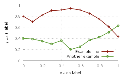
Fig. 1 Nice plot with the pngcairo terminal (code to produce this figure, data)

In Fig. 2 the default output of the pngcairo terminal is shown. I think the difference is quiet obvious.

not so nice plot

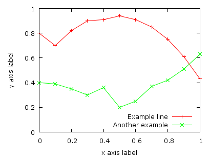
Fig. 2 Default output of the pngcairo terminal (code to produce this figure, data)

In the following I will have a look at the things we have to do to reach Fig. 1 and why we should do this:

1) change the default colors to more pleasant ones and make the lines a little bit thicker

set style line 1 lc rgb '#8b1a0e' pt 1 ps 1 lt 1 lw 2 # --- red
set style line 2 lc rgb '#5e9c36' pt 6 ps 1 lt 1 lw 2 # --- green

2) put the border more to the background by applying it only on the left and bottom part and put it and the tics in gray

set style line 11 lc rgb '#808080' lt 1
set border 3 back ls 11
set tics nomirror

3) add a slight grid to make it easier to follow the exact position of the curves

set style line 12 lc rgb '#808080' lt 0 lw 1
set grid back ls 12

The last thing I would like to mention is the problem, that the output of the svg terminal is slightly different from the pngcairo terminal. Especially the dashed line of the grid is not created in the right way, even though the dashed option is used for the terminal. This and a solution to convert the lines to dashed versions is also mentioned in the plotting the world entry.

nice plot with svg terminal

Fig. 1 Nice plot with the svg terminal (code to produce this figure, data)

July 11th, 2010 | 5 Comments

In the Gnuplot demo files folder that comes with your Gnuplot installation exists the file world.dat which contains data in order to plot a map of the world. Therefore we remove the key from the figure and set a grid (the dashed line in Fig. 1). Also we remove the tics by setting the format to nothing and the scale to zero. We could also remove the tics with unset tics, but the grid depends on the tics positions. After that we just plot the data:

unset key
set grid
set format ''
set tics scale 0
plot 'world.dat' with lines linestyle 1
The world

Fig. 1 A 2D plot of the world (code to produce this figure)

Here you can see a problem of the svg terminal of Gnuplot: it can’t produce dashed lines. In order to fix this, we can use Inkscape and open the svg file. Then pressing CRTL+F and type gray into the Style field and hit Enter. Now all the grid lines should be selected and you can set their stroke style to dashed by typing CRTL+Shift+F and choose one under Dashes. Doing so will lead to a figure shown in Fig. 2.

The world

Fig. 2 The 2D plot of the world edited with Inkscape

We can also easily draw a whole globe in 3D from the given data. Therefore we first add a gray line style, unset the border and arrange the figure margins.

set style line 2 lc rgb '#c0c0c0' lt 1 lw 2
unset border
set lmargin screen 0
set bmargin screen 0
set rmargin screen 1
set tmargin screen 1

The 3D plot needs a little more settings. We have to tell Gnuplot to map the data on a sphere and using angle values in degree. Also we want to have a non transparent world, therefore we need hidden3d. We arrange the appeareance of the plot by setting the xy-plane to the lowest z value in order to avoid an
offset between the lowest z vlaue an the xy-plane. To have Europe in the center we set also the viewport.

set mapping spherical
set angles degrees
set hidden3d
set xyplane at -1
set view 56,81

For the grid we have to remove the set grid command, because it doesn’t work with splot. So we draw the grid by our own using the parametric mode and finally plot the whole globe:

set parametric
set isosamples 25
set urange[0:360]
set vrange[-90:90]
splot cos(v)*cos(u),cos(v)*sin(u),sin(v) with lines linestyle 2, \
      'world.dat' with lines linestyle 1
The world

Fig. 3 A 3D plot of the world (code to produce this figure)

As you can see we have some problems with the data for Africa which lies behind the grid at some points. To avoid this and to make the grid dashed again we draw a grid with tinier radius and use Inkscape.

r = 0.99
splot r*cos(v)*cos(u),r*cos(v)*sin(u),r*sin(v) with lines \
      linestyle 2, \

In order to select the grid in Inkscape we have to search after the Style blue for some strange reason (on another PC green was the right color to search). You may have a look at the xml data to figure this out. Therefore under Edit you will find XML Editor. We not only set the stroke style to dashed we also lowered the selected objects
to avoid that any line of the grid covered a black world line. Having done all that we will finally get the nice globe in Fig. 4.

The world

Fig. 4 The 3D plot of the world edited with Inkscape